


Huawei P Smart (2019) Screen Replacement

Send this link via e-mail
|
Tweet |
|
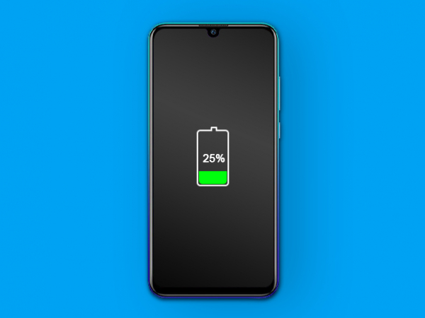


Step 1 - Before You Start
- Before you start disassembling the phone, discharge the battery to below 25%. - Turn off your Huawei smartphone. - Remove the SIM tray.
Caution:
- If the battery is swollen: - Take adequate measures and precautions, - Do not heat your phone, - Wear eye and hand protection.
Tip:
- If the display glass is broken, keep further breakage contained by taping over the glass. - Lay overlapping strips of clear self-adhesive tape over the display.
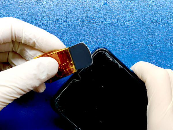


Step 2 - Opening The Phone
Back to top
- Use a thin opening tool to separate the back cover from the rest of the phone. - Start from the bottom right corner and go along the edges until all the clips pop off. - Lift the back cover to the left like opening a book. - The fingerprint sensor ribbon cable is attached to the phone right under the camera module. - Do not lift that side of the cover more than 1cm away from the phone.
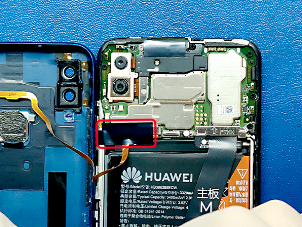


Step 3 - Connectors
Back to top
- Remove the black antistatic tape from the fingerprint sensor connector. - Remove 3 Phillips screws securing the metal connector shield. - Wiggle the shield out of the phone assembly. - Disconnect the 4 connectors: - Battery connector, - Touch id connector, - Display connector, - Logic board connector.
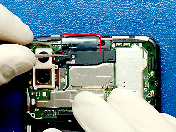


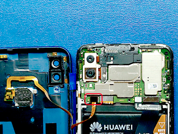
Step 4 - Motherboard
Back to top
- Remove the black antistatic tape from the top part of the motherboard. - Remove the 7 screws which secure the motherboard and the top bracket. - Remove the bracket that protects the front camera, sensors, and speaker. - Disconnect the antenna. - Unplug and remove the back cameras. - Remove the logic board.
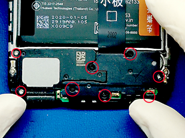


Step 5 - Bottom Logic Board
Back to top
- Remove the 8 screws that secure the speaker assembly and the lower logic board cover. - Remove the speaker assembly and the logic board cover. - Disconnect the logic boad flat cable. - Remove the logic board from the midframe.
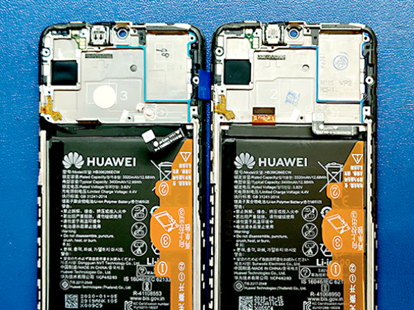


Step 6 - New Vs. Old Screen
Back to top
- Compare the new and old display assembly. - The spare part that we are using comes as an assembly: - The screen attached to the mid-frame, - The battery, - The speaker, - The vibration motor. - We will transfer the lower logic board the motherboard, and the cameras.
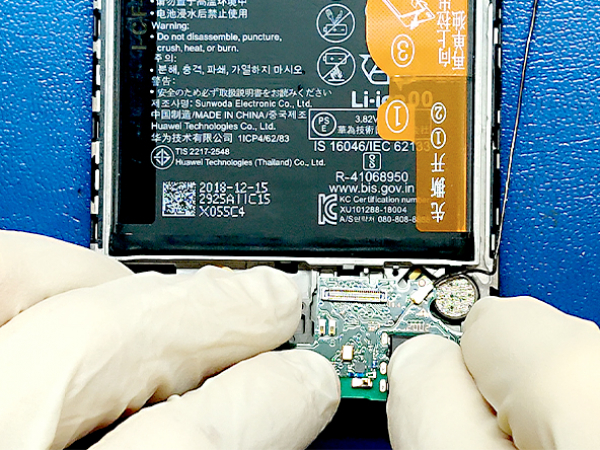


Step 7 - Transferring Parts
Back to top
- Insert the bottom logic board in the new display assembly. - Connect the logic board flat cable. - Install the speaker assembly and the board cover. - Secure them with 8 screws you removed in step 5. - Insert the mainboard and the front camera. - Connect all the plugs (display, logic board, antenna...) - Insert the back camera and reconnect it with the motherboard. - Install the top bracket. - Secure the 7 motherboard and top bracket screws.
Step 8 - Back Cover
Back to top
- Take the back cover and place it next to the phone. - Connect the fingerprint ID ribbon cable to the motherboard. - Insert the metal bracket/shield. - Secure it with 3 screws. - Connect the front and the back of the phone. - Press around the edges of the back cover. - Al the clips should click-in place. - Insert the SIM tray. - And the repair is done. - You can turn on your phone.